›› Rugged Ethernet and Timing Solutions


Modern time synchronization systems are based on the Precisions Time Protocol (PTP) according to the IEEE 1588 standard. PTP replaces dedicated time synchronization lines used for distribution of GPS data and IRIG-B.
The PTP Ground Master Clock of a network is the common time base source for all PTP Slave Clocks within the network. All Master Clock candidates are referred to as Ordinary Clocks and the best Ordinary Clock is selected as the Grand Master Clock based on the Best Master Clock Algorithm. All Ordinary Clocks not selected remain passive and can only enter Master Clock state if the chosen Grand Master Clock is removed from the network or is no longer the best candidate.
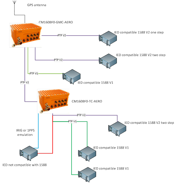
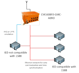
The switches in a PTP network should have PTP Transparent Clock support. Time synchronization packets forwarded through a switch with PTP Transparent Clock support will not suffer from variable switch latency. The switches in the network should have Slave Clock support, meaning they are synchronized with the PTP Slave Clock end devices to the same Grand Master Clock. A switch on the edge of the network can then provide non-PTP interfaces with time synchronization output signals such as IRIG-B (DC and AM) or GPS emulation (i.e. 1PPS and NMEA telegrams) in order to distribute time to non-PTP end devices
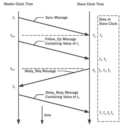
This section describes the PTP message sequences that occur during synchronization.
The PTP clocks configured for End-to-End delay mechanism use the following PTP messages:
These messages are sent in the following sequence:
The Slave Clock receives a Delay_Resp message from the Grand Master Clock with time stamp (t4). After this sequence, a Slave Clock possesses all four time stamps that can be used to compute the offset of the Slave Clock relative to the master, and the propagation time between the two clocks.
The offset calculation is based on the assumption that the uplink and downlink propagation times are the same.
The Transparent Clock (TC) mode is implemented in each network switch. The TC functionality corrects the residual latency introduced by the network node. It also adjusts the time stamp in accordance with the switch residence time and forwards the synchronization messages to the next network node in the chain.
The need for PTP version translation is driven by the fact that PTPV1 (IEEE 1588 2002) is not backward compatible with PTPv2 (IEEE 1588 2008). Both PTP versions cannot co-exist in the same network unless a PTP version translator is used.
Ref to paper PTPv1 and PTPv2 translation in FTI systems
The PTP version translation feature protects your PTPv1 investments. You can use your legacy PTPv1 equipment together with your new PTPv2 equipment by using the PTP version translator of OnTime Networks.
No need to upgrade or change configuration of old PTPv1 equipment